DeviceTest Test
1. TXV : Check the evaporator coil and remove the TXV's sensing bulb from the suction line. Or, melting all prost in evaporator, balance low and high side pressure to check refrigerant level before have a solution. If it is ok, turn on the system and follow to see whether frost or not. If prost, bad TXV
_ Check SH and SC again, if no change => TXV broken
_ To make sure, put TXV into ice water, if SH, SC no change => TXV is broken for sure
Or: If the SH stops dropping while charging and the SC continues to increase chances, having a good TXV
Turn adjustment clockwise to increase superheat, counter‐clockwise to decrease superheat. To return to approximate original factory setting, turn adjustment stem counterclock‐wise until the spring is completely unloaded (reaches stop or starts to "ratchet"). Then, turn it back in one half of the "Total Turns" shown on the chart. Low charge => high SH, due to input side is so too cold that frozen => CWW to decrease SH
2. Filter drier: If temperatures of both ends of the device is so much different (>2 F)=> bad drier
3. Pressure valve: Much different in temperature (>5F), can be felt. R=~12Ω
4. Gas valve (furnace) : Input =8.00, Output = 3.50 WC when burning.
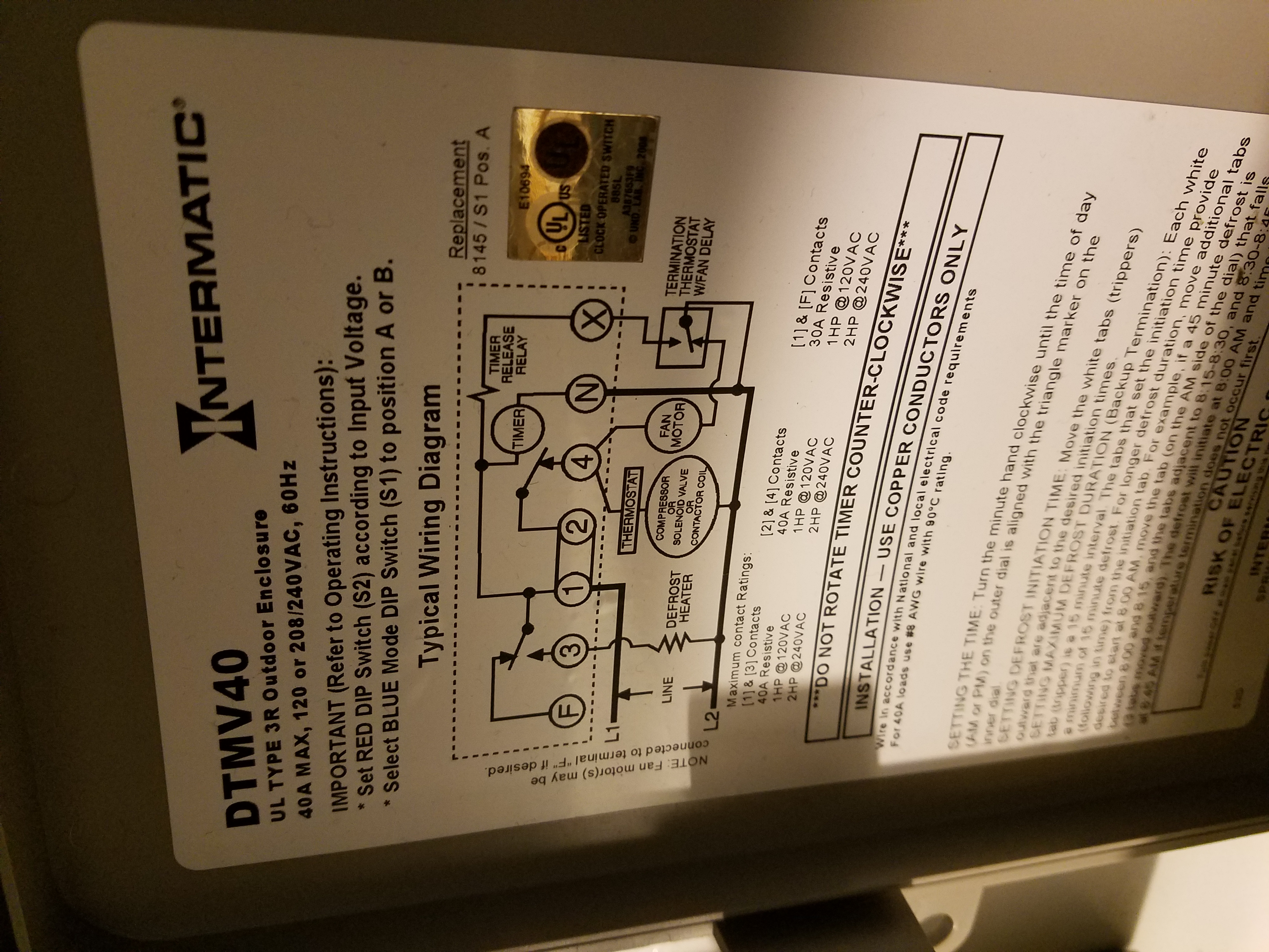
1. Move the needle to check defrost cycle (check current)
2. Blower fan often has a thermostat in order to delay the fan sometimes upto 15mns to work
4. Zone Control : M1 (com), M4 (Open), M6 (Close); [Often wiring M1-M6 Normally Open]. It means when energized damper with M6 will close (Điện_Đóng). Diagnostics: Turn on all zones and mark all positions of all dampers. Then turn off all zones (T'stats) and check which damper is still to stay (could be closed)=> this damper is the problem one (A). To confirm, check whether 24v or not at (A) to see whether different status or not when 24v and not 24v to conclude bad damper motor or not. Turn On (Fan only) at good zone and system Off (auto fan) at bad zone => if (A) has no 24v => bad board,....NOTES: On/OF good zone t'stat to check bad other damper.
Which zone called won't have 24 v=> damper open while other zone won't called, having 24v => close dampers. Which zone called, damper is still no power and open while other dampers will energy and close. When system turn off, all damper motors have no power and all dampers are in open position. So to check damper motor: Turn off all zones, then bypass motor with 24v one at a time. If all motor bypassed is OK, connect all them back and check 24v motor onboard to recognize bad board or bad motor for sure...... and check whether there is any close. If have, wiring 24v to see it moves/not. Set damper: Position damper at open and drive screw tightly (no power)
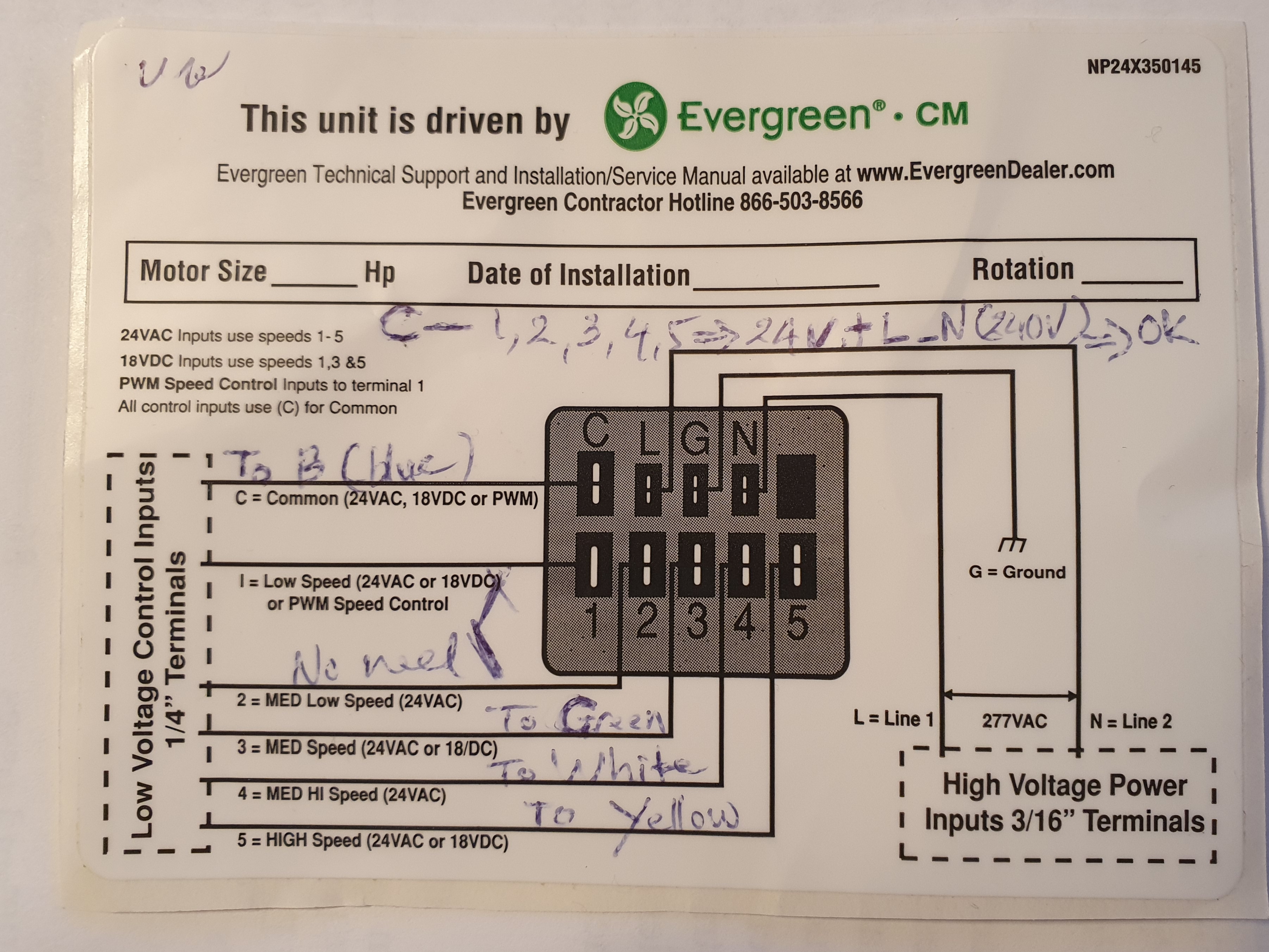
5. ECM motor 9 Pins: Wiring chart . package unit (gas and heat pump) and split heat pump =>220v. C and one among (1,2,3,4,5) wires = 24 v. N G L C is source power. [N_L=220v]
ECM 16 wires testing with TECInspect . 1. Connect 16 wire socket from tool to motor. 2.Keep power (120 or 240v) socket in motor. 3. Connect tool to 24v with clamps. 4. Turn tool on, light will be On and fan will run. (A). Motor not run =.bad motor, (B) Motor run, bad board.
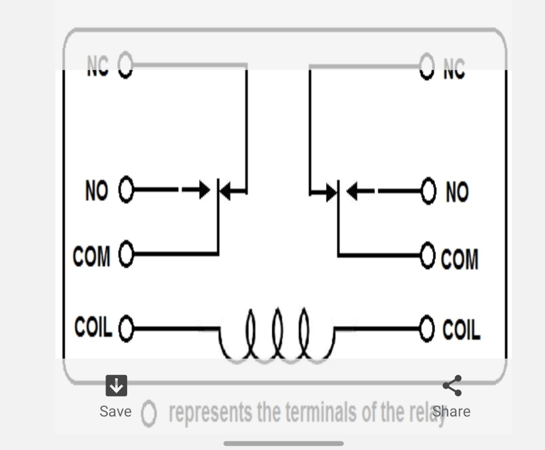
Fan Relay : looks like for Lennox heat pump
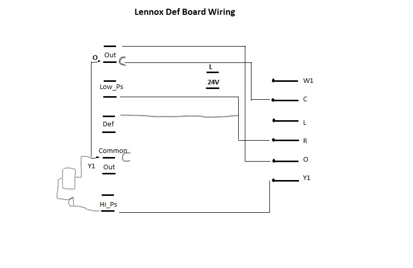
Lennox Def Chart
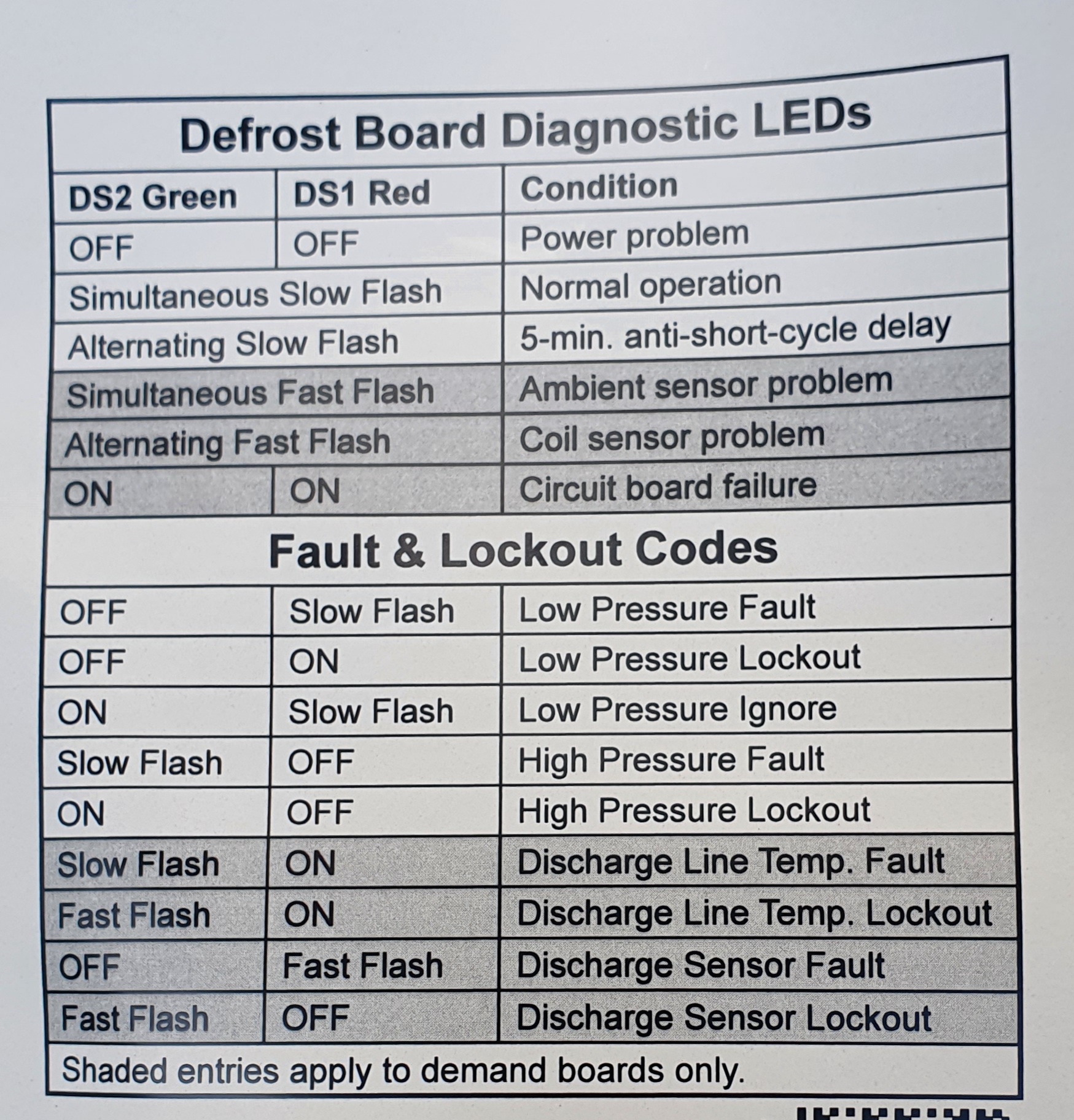
Lennox Heat Pump light code
Lennox Furnace light code
Lennox Heat Pump Gas Valve check: Active with 24v power whether there is a noise. If not having a noise, Use a new gas valve (24v) to try whether gas valve open or not => Gas valve or board is bad
6. Reversing valve : structures
7. Copeland Motor
How to read ZP49K6E-TF5-830